 If any of you had a look at FireMonkey’s TCube object, you might have noticed rendering it is quite slow and quite complex.
If you were curious enough to look at the code, you might have noticed that TCube is actually a static mesh made up of 452 vertices, 1440 indices and 480 triangles, instead of the 8 vertices and 6 quads (12 triangles) one could have expected.
That explains why it’s slow… and when looking at the indices, there are more oddities: some coordinates aren’t properly rounded (you can find -1.11759E-8 instead of zero), normals aren’t normalized, and the tessellation doesn’t seem to be the same for all the faces. There is probably an interesting story behind that cube…
That said, why would one want such a complex cube? Though none of the uses described below apply to TCube, it allows to introduce the subject of tessellation.
Per-Vertex lighting
When lighting an object in 3D, there are two ways to go about it, the historical one (before pixel shaders) was to use per-vertex lighting, with per-pixel linear interpolation, aka “Gouraud shading”. In such a case, if the light is close to the cube, or if the cube is fairly large, you would have artifacts, because the lighting wouldn’t be computed everywhere.
Using GLScene, I’ve illustrated the effect below on a single face (click to enlarge) of the effects of subdividing on per-vertex lighting, you can also download the source + precompiled executable (403 kB) if you want to see it more interactively
The closer the light is to a surface, the more subdivisions you need, which means that to get correct lighting with per-vertex lighting, you need a fairly high triangle count. Hence this technique wasn’t too practical, and you usually had to go for tricks (such as using lightmaps, decals, etc.) or vary the subdivision dynamically to minimize the performance impact. F.i. even though the FMX TCube is quite heavy, it’s nowhere near as heavy enough to achieve good per-vertex lighting quality with a close light-source.
Nowadays however, you have hardware pixel shaders, which allow you to compute lighting not per-vertex, but per-pixel, so you can obtain an image similar to the rightmost one above, with only two triangles.
 Deformations and vertex shaders
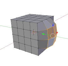
Deformations and vertex shader maths are one first use, like in the Blender picture to the right.
A common mesh manipulation tool, linked to deformation or extrusion tools,is to start from a basic geometric form, with more triangles than strictly necessary, and work on those triangles to achieve a not-basic geometric form.
Another use would be to make a dynamically deforming cube, that would bounce and warp at runtime. For that you would need a vertex shader or CPU-side geometry processing. A variant would be displacement maps, but that usually requires a high number of vertices.
In both those case however, you’ll obviously want to control how much the faces should be subdivided, and in practice, you’re entering the area of controlled mesh tessellation, and leaving that of a simple cube object.


Great insights … as usual !
For those interested into OpenGL internals here are some nice and easy to follow tutorials (including the full source code) OpenGL Step By Step http://ogldev.atspace.co.uk/
Keep the good work …
For a higher level sharder development I recomend these DirectX (HLSL) and OpenGL (GLSL) shader IDEs:
AMD RenderMonkey
http://developer.amd.com/archive/gpu/rendermonkey/pages/default.aspx
NVIDIA FX Composer
http://developer.nvidia.com/fx-composer
Unfortunatelly, these are a bit old but I have no clue about any replacements available
AFAIK there aren’t any replacements, because the relevance of such tools has gone away.
On one side, game engines have too many specific and particular rendering paths, which don’t fit into a generalist shader tool.
On the other side, higher level engines usually synthesize shaders based on high level material descriptions.
Hand-written shaders are slowly becoming something which isn’t manually edited, except by a very small number of persons, in specific situations.